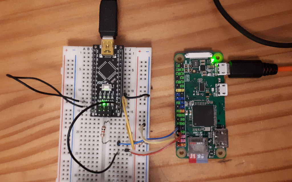

Recently I needed to access a Raspberry Pi via a serial console. Unfortunately all my 3.3V USB serial adapters were already
in use in other projects that I didn't want to disassemble for one reason or another.
I did have several Arduinos at hand, though, so I simply used one of those as an improvised adapter.
While that in itself is not particularly remarkable, I find myself doing this on average
a couple of times a year. Basically whenever I need and UART adapter but don't have one at hand.
And every single time I need to look up pinouts or wiring diagrams and the correct resistor values.
So this time I decided to write a short blog post about it so that I'll find the information more
quickly the next time I need to do that.
Many Arduino style boards use an USB to serial adapter chip like a FT232RL or a CH340G for USB communication. In this case
I'm using an Arduino Nano clone but the same applies to e.g. Arduino Unos and their clones.
Since this chip is the same one that would be used in an off the shelf USB to serial adapter cable, an Arduino board can
be used as a replacement for such a cable by simply grounding the AVR controller's reset pin. This way the TX and RX pins of the
serial chip can be accessed through the respective pins on the board header.
When doing this there are two potential pitfalls to keep in mind: Correct wiring and voltage levels.
Usually when connecting two devices by UART you will hook up one device's receive line (RX) to the other device's
transmit line (TX). While this is exactly what we are going to do here, the markings on the Arduino board will be
misleading since we are not using the board quite as intended.
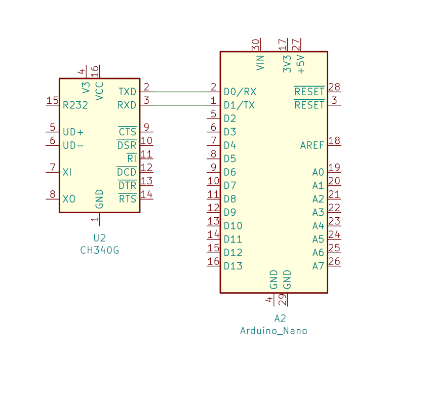
The UART pins on the Arduino board are marked TX and RX (pins 1 and 2 on an Nano). Those markings describe the functions
of those pins as they are attached to the main AVR controller. Since we are going to disable the AVR by grounding it's
reset pin and using those pins to talk to the serial adapter chip instead, the functions of those pins are exactly reversed.
The pin marked TX is connected to the RX pin of the serial chip and the pin marked RX is connected to it's TX ping.
This might be easier to understand by looking at this picture:

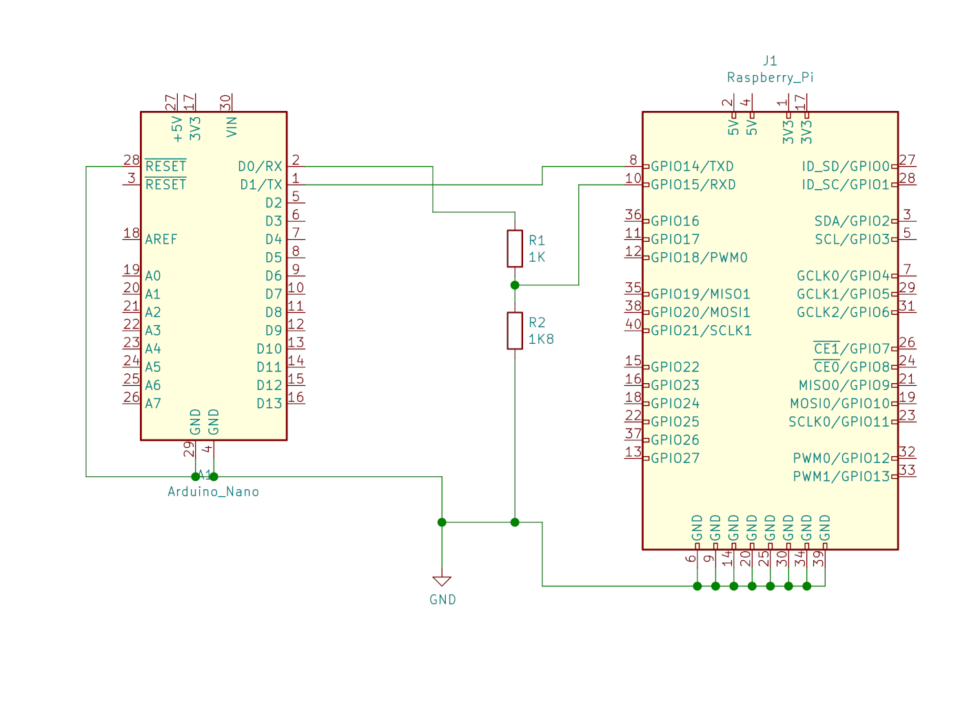
So instead of connecting our target device, in this case a Raspberry Pi Zero W, as we usually would, TX-RX and RX-TX, we need to connect the RX pin on the RasPi to the RX pin on the Arduino and therefore also the TX pin on the RasPi to the TX pin on the Arduino.
The proper wiring can be seen in this picture:

As you might have guessed from the above picture simply connecting the RX and TX pins is not enough.
The other problem here is that the Arduino runs on 5V whereas the Raspberry Pi runs on 3.3V. For communication from the
RasPi to the Arduino this is not a problem since the serial chip on the Arduino will recognize 3.3V as a "high" level and
therefore process signals correctly.
Supplying the RasPi's RX pin directly with 5V from the Arduino's TX pin can, and probably will, lead to permanent damage
of the RasPi's UART!
Therefore we need to reduce the voltage on the RasPi's RX line to a level it can handle.
The proper way to do that would be to use a transistor for level shifting (which could also be used in the reverse
direction to convert the RasPi's 3.3V signal to the correct 5V signal for the Arduino). But we're not going to do that
here because we just want a reliable but quick and dirty solution.
So what we're going to do instead is use two resistors to create a voltage divider that will reduce the 5V signal to
about 3V which the RasPi can handle and process correctly.
As can be seen in the above image I'm using an 1k Ohm and an 1.8k Ohm resistor which will give me about 2.9V on the RasPi
side with my particular Arduino clone. While this should work just fine in most cases, you could go as high as about 1k and 2k
if you don't get a good signal with the smaller resistor.
For the correct wiring of the resistors please also refer to the above image.
Now that the hardware is set up properly we only need to enable the serial console on the RasPi so we can actually see some output there. This is easily done by adding the following line to the /boot/config.txt file on the RasPi's SD card:
enable_uart=1
With the console set up and the hardware connected we can see the RasPi's serial from Linux by connecting the Arduino to an USB port, powering up the RasPi, and connecting to the serial port using screen:
# screen /dev/ttyUSB0 115200
That's it for today. And as always, if you have any questions or comments, don't hesitate to contact me via email or twitter.